Copyright © 2025 Chuangming Coupling (Jiangsu) Co.,Ltd.
The loads borne at the bearings on both ends of the coupling
2026-07-03
The load distribution on both sides of the coupling increases with increasing misalignment at that location, while it decreases under the influence of misalignment at the bearings at both ends of the system. The load distribution at the end bearings decreases as the misalignment at the coupling supports increases, but increases under the influence of local misalignment at those bearings themselves. The shaft deflection within a bearing is referred to as bearing misalignment; however, bearing misalignment alone does not generate vibration.
When rotors in a unit are connected by couplings, if their axes are not aligned along the same straight line, this condition is known as shaft misalignment. Misalignment generally refers to shaft misalignment. When rotor systems experience misalignment, axial and radial alternating forces are generated, leading to axial and radial vibrations. Consequently, a series of dynamic effects detrimental to equipment operation occur during motion. The dynamic characteristics of misaligned rotor systems are therefore significant for the operation of the unit.
Under the influence of misalignment at the bearings on both sides of the coupling, certain trends emerge: as misalignment increases, the system's logarithmic decrement decreases and the instability speed drops. In terms of radial stiffness of the coupling, the angular stiffness determines its vibration isolation performance. Angular stiffness is a key factor affecting the coupling’s vibration isolation capability. When the system passes through the critical speed range, rotor misalignment significantly influences the system’s unbalance response, although this effect diminishes at operating speeds.
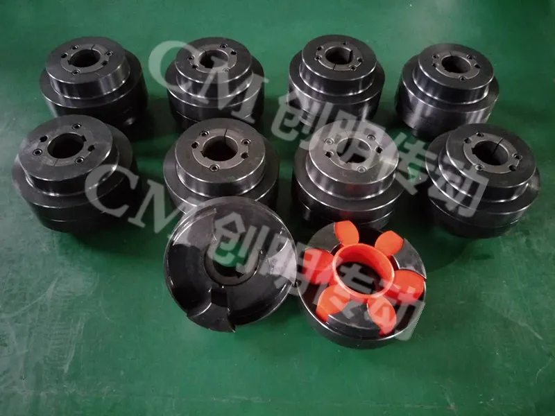
Couplings allow the connected shafts to undergo displacement in any direction, essentially providing angular compensation. The internal gear ring and external gear sleeve of the coupling form a special intersecting-axis meshing transmission pair, offering excellent ability to compensate for arbitrary directional displacement between shafts. The outer gear tooth tips are designed as spherical surfaces located on the axis, and appropriate tooth side clearance must be maintained in the meshing pair. Insufficient side clearance fails to meet the requirements for angular compensation.
The load distribution on both sides of the coupling increases with increasing misalignment at that location, while it decreases under the influence of misalignment at the bearings at both ends of the system. The load distribution at the end bearings decreases as the misalignment at the coupling supports increases, but increases under the influence of local misalignment at those bearings themselves. The shaft deflection within a bearing is referred to as bearing misalignment; however, bearing misalignment alone does not generate vibration.
When rotors in a unit are connected by couplings, if their axes are not aligned along the same straight line, this condition is known as shaft misalignment. Misalignment generally refers to shaft misalignment. When rotor systems experience misalignment, axial and radial alternating forces are generated, leading to axial and radial vibrations. Consequently, a series of dynamic effects detrimental to equipment operation occur during motion. The dynamic characteristics of misaligned rotor systems are therefore significant for the operation of the unit.
Under the influence of misalignment at the bearings on both sides of the coupling, certain trends emerge: as misalignment increases, the system's logarithmic decrement decreases and the instability speed drops. In terms of radial stiffness of the coupling, the angular stiffness determines its vibration isolation performance. Angular stiffness is a key factor affecting the coupling’s vibration isolation capability. When the system passes through the critical speed range, rotor misalignment significantly influences the system’s unbalance response, although this effect diminishes at operating speeds.
Couplings allow the connected shafts to undergo displacement in any direction, essentially providing angular compensation. The internal gear ring and external gear sleeve of the coupling form a special intersecting-axis meshing transmission pair, offering excellent ability to compensate for arbitrary directional displacement between shafts. The outer gear tooth tips are designed as spherical surfaces located on the axis, and appropriate tooth side clearance must be maintained in the meshing pair. Insufficient side clearance fails to meet the requirements for angular compensation.
Previous: No more data